Notes on emulators
An overview of video game console emulators. Some time ago I coded Kiwi, a simple emulator of the Sega Genesis system. I wrote down some information that was useful to me in making Kiwi. It is by no means exhaustive, but it might be of some interest.
A video game console emulator is a piece of software designed to emulate the workings of a video game console well enough to make it possible to run games designed for that console on a different system – usually a personal computer or a modern console. Typically people use emulators to play games from long obsolete consoles.
Fans also use emulators to run video game modifications unapproved by the manufacturers of the console, such as fan translations and hacks.
Emulation
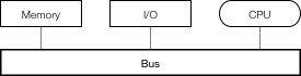
Most computers produced after the 1940s implement the Von Neumann architecture, which consists of a processing unit (a CPU), memory and input and output mechanisms. These subdivisions share a common bus, a subsystem that transfers data between components.
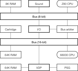
An emulator has to emulate all of the components of a computer architecture as well as their interoperation. An example of such an architecture is the one implemented in Sega Genesis. It consists of two general-purpose processors, three Random Access Memory (RAM) modules, a Video Display Processor (VDP), a Sound processing unit, a Programmable Sound Generator (PSG), input and output (I/O), peripherals and a replaceable cartridge that holds the program data. As some of the components are 8-bit and some are 16-bit, there are 8 and 16-bit buses and a bus arbiter. Each bus consists of control, address and data buses.
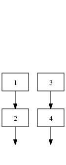
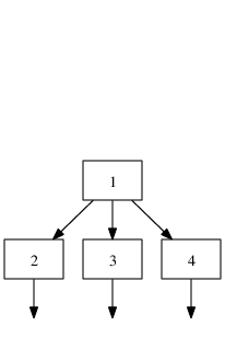
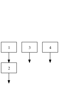
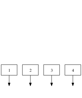
Emulators are primarily written hobbyists. Because of this, there is no unifying theory on how to emulate computer systems. There is however, one thing that emulators share, and that is the main loop. Each component is run for a number of steps, usually equivalent to a fraction of a second (e.g. a frame — there are 60 frames in a second on a 60 Hz display). Then, synchronization is performed between the components.
while not finished:
    for component in components:
        component.run_for_some_time()
    synchronize()
Accuracy
Although at first glance it may seem like the best way to go about emulating each component is to emulate it as accurately as possible, accuracy comes at a significant cost in performance. Whether performance or fidelity is more important depends on the requirements of a given emulation project.
The possible accuracy levels have been classified by Joshua H. Shaffer into classes of decreasing accuracy.
Data-path Accuracy
The highest level of accuracy. Emulators in this class simulate the physical characteristics of a component, down to the data-path level. One use of this is historical preservation, as seen in the interactive Visual 6502 simulator which simulates a 6502 CPU down to the transistor level by working with digitized microscopic photographs of the CPU. This is the slowest method of emulating a chip — the Visual 6502 simulator runs at 27 Hz on a modern computer, which at 2 GHz is a slowdown by a factor on the order of 75 million.
Cycle Accuracy
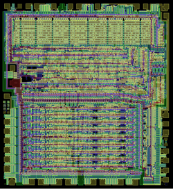
Vectorized layers of the 6502 CPU, courtesy of Visual6502.org
It forgoes emulating the precise workings of a chip, instead only requiring faithful emulation of the underlying Instruction Set Architecture (ISA) and the timings of instructions relative to each other. Typically, precise timings are only required on old 8 and 16-bit architectures, where programmers could depend on the timings for certain effects. An example is VICE which emulates Commodore 64 cycle-accurately.
Instruction-level Accuracy
A fairly common choice as it is a reasonable accuracy vs speed trade-off. It is mostly concerned with accurately emulating instructions and their side effects while ignoring their precise timing. In some instances consideration should be given to undocumented CPU instructions, as games might depend on undocumented behavior.
Basic-block Accuracy
It allows replacing larger blocks of code with native code equivalents. This method is faster than instruction-level accuracy but it does not allow single-stepping through code and does not work with code that relies on its original form, such as self-modifying code. The Amiga emulator UAE is an example.
High-Level (HLE) Accuracy
HLE identifies structures in code that can be replaced by native high-level functionality. Recent gaming consoles are often emulated by detecting audio and video library code calls and replacing them by native library implementations without ever executing the original library code. The Nintendo 64 emulator UltraHLE is famous for being the first emulator of this kind. At the time of its release, 1999, a mere 3 years after the release of the Nintendo 64, it ran commercial titles at a playable frame rate on the hardware of the time. This approach had its drawbacks; at the time of release, UltraHLE was only able to emulate approximately 20 games to a playable standard.
Generally, faster emulation means less accuracy and vice versa.
| Emulator | Accuracy class | Slowdown factor |
|---|---|---|
| Visual 6502 | Data-path | 75 million |
| VICE | Cycle | 250 |
| UltraHLE | HLE | 3.7 |
Speed comparison of three emulators from distinct classes
System emulation
Typically a computer system has one or more address buses, in which addresses and address ranges are assigned to components. For example, the Sega Genesis has two address buses, as shown below.
| Device | Address (hex) |
|---|---|
| 16-bit bus | |
| Cartridge | 000000-3FFFFF |
| 8K RAM | A00000-A01FFF |
| Sound processor | A04000-A04003 |
| I/O | A10000-A1001F |
| VDP Data | C00000 |
| VDP Control | C00004 |
| PSG | C00011 |
| 64K RAM | FF0000-FFFFFF |
| 8-bit bus | |
| 8K RAM | 0000-1FFF |
| Sound processor | 4000-4003 |
| Bank register | 6000 |
| PSG | 7F11 |
| Banked memory | 8000-FFFF |
Simplified Sega Genesis address map
Memory mappings fall under two categories:
-
Linear mapping — an address range is translated to a corresponding physical address range and address lines are used directly without any decoding logic, for example in accessing physical memory.
-
Direct mapping — a 1:1 mapping of a unique address to one hardware register or a physical memory location.
As seen in the Sega Genesis example, memory maps often contain holes. For simplicity of circuit design, certain mappings are mirrored, for example on the Sega Genesis, the RAM address 1234 can be accessed by accessing FF1234 as well as EF1234.
Components send signals called interrupts, of which there are two types. A hardware interrupt is a signal from a component indicating it needs attention. A software interrupt is a CPU instruction. When a CPU receives an interrupt, it suspends its current state of execution and begins execution of an interrupt handler. This usually invokes an exception appropriate to the kind of interrupt.
Interrupts are typically used for signaling from components, timers and traps (user interrupts). A simplified exception table for the main CPU in the Sega Genesis system is shown blow. On the Genesis, the VDP (video processor) fires a Vertical Blank interrupt every vertical blank, which occurs at the start of every displayed frame (50 times a second on a PAL TV and 60 on an NTSC TV), which is useful for timing-dependent functions. The VDP also signals a Horizontal Blank interrupt every horizontal blank, which occurs after a line has been displayed (about every 10 μs). Finally, there is an external interrupt. One of its uses was to tell the game a light gun has been fired.
| Type | Number | Exception |
|---|---|---|
| Reset | 0 | Reset Initial Stack Pointer |
| 1 | Reset Initial Program Counter | |
| Errors | 2 | Access Fault |
| 3 | Address Error | |
| 4 | Illegal Instruction | |
| 5 | Integer Divide by Zero | |
| Traps | 6 | CHK Instruction |
| 7 | TRAPV Instruction | |
| 8 | Privilege Violation | |
| 9 | Trace | |
| 10 | Line 1010 Emulator | |
| 11 | Line 1111 Emulator | |
| Interrupts | 24 | Spurious Interrupt |
| 25 | Level 1 Interrupt (Unused) | |
| 26 | Level 2 Interrupt (External) | |
| 27 | Level 3 Interrupt (Unused) | |
| 28 | Level 4 Interrupt (Horizontal Blank) | |
| 29 | Level 5 Interrupt (Unused) | |
| 30 | Level 6 Interrupt (Vertical Blank) | |
| 31 | Level 7 Interrupt (Unused) | |
| Traps | 32-47 | Trap #0-15 Instructions |
Sega Genesis exception vector table for the 68000 CPU
CPU emulation
Michael Steil describes three approaches to emulating CPUs in his PhD thesis: interpretation, recompilation and a hybrid method.
Interpretation
Interpretation is the simplest way of emulating a CPU. An interpreter directly simulates the fetch-decode-execute cycle. That is, until the emulator is shut down, it fetches an instruction, decodes and executes it, then another, and so on.

while not finished:
    # fetch
    instruction = memory[IP]
    IP += 2  # increment the instruction pointer register

    # decode
    if instruction == 0x4e71:  # execute NOP instruction
        pass

    else if (instruction >> 8) == 0:
        # decode and execute an ORI instruction

        # decode the appropriate effective address
        size = (instruction >> 6) & 3
        ea_mode = (instruction >> 3) & 7
        ea_register = instruction & 7
        ea = get_ea(ea_mode, ea_register, size)

        # OR the effective address by an immediate value
        *ea |= get_immediate(size)

        set_flags()

    else if (opcode >> 8) == 1:
        ...
Interpretation is slow — for every original instruction a couple dozen native instructions are executed. Additionally, modern CPUs take advantage of a technique called pipelining, which allows them to execute many instructions at once, as long as it is possible to predict what instructions will be called in advance. A simulated fetch-decode-loop makes predicting future instructions impossible, thus modern CPUs are often unable to use pipelining in interpreter code.
Recompilation
Recompilation translates emulated code to native code. It takes advantage of the fact that it is unnecessary to decode instructions every time they need to be executed, and moves the decoding part to the pre-processing phase of the emulator.
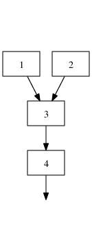
Threaded recompilation is the simplest form of recompilation. It simply replaces each original instruction with a library call to a native code implementation of the original instruction.
  move.w  7, d0
  addi.w  d1, d0
  ori.w   1, d0
move(1, 7, 0)
addi(1, 1, 0)
ori(1, 1, 0)

ori(size, source, dest):
   d[dest] |= d[source]
   set_flags()
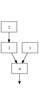
Real recompilation, on the other hand, translates original code into native code directly, without the need for instruction function calls.
Recompilation can be done ahead-of-time (before execution) or just-in-time (JIT) — during execution.
Static recompilation
Static recompilation is ahead-of-time recompilation. A statically recompiled program is indistinguishable from a native program and does not contain any translation logic.
Like normal ahead-of-time compilers, static recompilers can perform global optimizations on programs, resulting in fast execution time. This comes at a cost, however, as static recompilation is a hard problem. Programs on Von Neumann architectures frequently intertwine code and data and recognizing what is code and what is data might be hard or impossible, depending on the architecture.
To illustrate this, a jump table, below, is a piece of code that loads an address based on an index and then jumps to it. In the example, if index holds the number 0, the code will jump to Level and if index holds 1, the jump will be to Title.
The problem is, a recompiler does not know how many entries there are in the jump table, so it can’t know whether 02427fff (the machine code representation of the andi.w instruction) is an instruction and therefore an address to jump to, or not.
  move.w  (index).w,d0
  lsl.w   2, d0     ; d0 *= 4
                    ; (addresses are 4 bytes long)

  move.w  JumpTable(pc,d0.w),d0
  jmp     JumpTable(pc,d0.w)

JumpTable:
  dc.l    Level
  dc.l    Title
  dc.l    Ending
  dc.l    Credits

Level:
  andi.w  $7FFF,d2  ; 02427fff in hex
Video games up until the 1990s were often written in assembly, and used techniques harmful to static analysis, such as self-modifying code. Some seemingly harmless practices, such as decompressing, decrypting or loading code into memory are as hard as self-modifying code for recompilation purposes.
If you want to write a completely accurate recompiler that works on arbitrary input, these issues make it difficult. But often this is unnecessary. If you only want to recompile a specific game, it suffices to play through the game completely, logging what is code and what is data with an interpreting emulator and then to perform static recompilation. An example of this is a Ms Pacman recompilation by Neil Bradley.
Dynamic recompilation
A dynamic, or just-in-time (JIT) recompiler translates original code to native code on the fly and then caches the resulting native code for later execution. Although translation of a single piece of code is more computationally expensive than interpretation, most of the execution time in a program is usually spent in relatively small loops. A JIT recompiler only has to translate a loop once, but it can run the loop thousands of times, so for an average program this is an overall speed improvement.
JIT recompilers do not have to possess advance knowledge of what is code and what is data, since only valid code paths will be translated. JIT also solves the problem of self-modifying code. If a code modification is detected, the code can be marked as dirty for later recompilation.
Hotspot method
The hotspot method, first used in the HotSpot Java virtual machine, aims to combine the best of both worlds — the speed of interpreters in rarely executed code, and the speed of JITs in code that is executed often. It does so by interpreting by default and identifying hot spots of often-run code and marking it for recompilation. The average cost per execution is visualized below. For typical values of ce, ci and cr (2, 10 and 50 respectively) the hotspot method approaches dynamic recompiling in terms of cost for often executed code, while maintaining the fast speed of interpreting code that is only run once.
| Method | Cost | ||||
|---|---|---|---|---|---|
| Interpreter | nci | ||||
| Dynamic recompiler | cr + nce | ||||
| Hotspot method |
|
| ci | cost of a single interpretation of the code |
| cr | cost of translating the code |
| ce | cost of running the translated code |
| n | number of times the code is to be emulated |
| t | number of times the code is interpreted before it is translated |
Cost formulas for an interpreter, a dynamic recompiler and the hotspot method
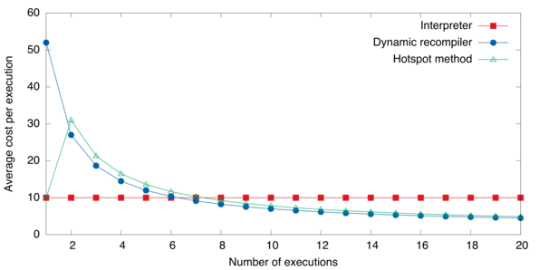
Average cost graph for different emulation methods
Graphics emulation
Graphics and music hardware is varied but there are some general concepts. Emulating a specific component consists of figuring out its functionality and replicating it.
A video display (such as a TV) displays graphics composed of pixels and refreshes at a specific rate (typically 50 or 60 times per second). A pixel is the smallest controllable element of a picture. A game console processes graphics and then sends them to the video display at a specific resolution. For example, the Sega Genesis is capable of outputting 240 lines each consisting of 320 pixels (this is typically referred to as a resolution of 320×240). Video game consoles usually have a distinct video output device which processes graphics and outputs video signal.
Framebuffers
The simplest video output device is the framebuffer, which drives a video display from a memory buffer containing a complete frame of data.
The memory buffer typically consists of color values for each pixel on the screen. The number of values each color value can take is the color depth, and this is the number of colors the device can display simultaneously. The higher the color depth, the more bits it takes to store a single color value, and in turn, the more memory is needed to store the frame buffer. For example, a 24-bit 800×600 frame buffer needs 800 · 600 · 24 · 1/8 = 1 440 000 bytes, or 1.4 megabytes of memory, while a 4-bit one with the same resolution only needs 800 · 600 · 4 · 1/8 = 240 000 or 234 kilobytes of memory.
In order to save memory and storage, a technique called indexed color is used where instead of a full color buffer, an indexed buffer is used. With this technique, color information is stored in a buffer called a palette in which every color is indexed by its position in the palette. Instead of full color values, an indexed buffer stores palette indexes for each pixel. An example indexed image in 1, 2 and 8-bit color depths is shown below. This method was used in numerous systems. For example, the Sega Genesis has a palette that can hold up to 64 different colors selected from 512 possible color values.
 |  |
| 1-bit | 24-bit (truecolor) |
 |  |
 |  |
| 2-bit and palette | 8-bit and palette |
1, 2, 8-bit indexed color pictures and original 24-bit color picture
| Color depth | Number of colors | Used in |
|---|---|---|
| 1-bit | 2 | Atari ST |
| 3-bit | 8 | ZX Spectrum |
| 4-bit | 16 | Amstrad CPC |
| 6-bit | 64 | Sega Genesis |
| 8-bit | 256 | Atari TT, AGA, Falcon030 |
| 11-bit | 2048 | Sega Saturn |
| 12-bit | 4096 | Neo Geo |
Indexed color depth used in a number of systems
Tile-based graphics
To save memory and storage even more, instead of directly controllable framebuffers some systems implement a tile-based method of storing graphics data in memory. Using this method, screens are composed of tiles instead of individual pixels. In turn, the tiles are composed of pixels. This is illustrated below. The video hardware composes the tiles on the fly in each frame or line instead of keeping it in memory. This approach made it possible to reuse frequently occurring tiles, such as skies, empty space and other repeating patterns.

As an example, in the Sega Genesis, the screen is composed of two main tile planes and one auxiliary plane. The main planes can hold 4096 tiles each. Each tile is 8×8 pixels and video memory holds approximately 1300—1800 distinct tiles at a time. Each tile could be displayed in one of four palette lines, further promoting reuse of tiles. A plane decomposition of the above screenshot is shown below.
 |  | |
| Foreground plane | Background plane | Sprite plane |
 | ||
| Tiles in video memory | ||
Sprites
Apart from backgrounds and foregrounds, objects (such as the player character, enemies, items) are a common occurrence in video games. Unlike backgrounds and foregrounds which typically fit well into tile-based graphics, objects could move in arbitrary ways, making tiling difficult. Because of this, consoles used to incorporate sprites into their video graphics hardware.
Sprites are bitmaps which can be moved on the screen without altering the data defining the rest of the screen. This introduced considerable space and bandwidth savings, as instead of modifying the entire affected area of the screen every time an object was to be drawn, the game only had to send a small sprite frame to the graphics hardware. This was useful for animated objects as only the sprite frame had to be changed in an animation.


Implementing sprites in hardware was an opportunity to relieve software from doing some work that is common to working with sprites. One such example is scaling and rotation, which was implemented on the Game Boy Advance system. A common feature was to perform collision detection.
| Game Boy Advance | Neo Geo | Sega Genesis | SNES | |
|---|---|---|---|---|
| Sprites on screen | 128 | 384 | 80 | 128 |
| Sprites on line | 128 | 96 | 20 | 34 |
| Max sprite size | 64×64 | 16×512 | 32×32 | 64×64 |
| Colors | 15, 255 | 15 | 15 | 15 |
| Scaling | Yes | Shrinking | - | Limited |
| Rotation | Yes | - | - | Limited |
| Collision detection | - | - | Yes | Yes |
Sprite hardware capabilities for several systems
Vector displays
A vector display are much less common. In a vector display, an image is composed of lines instead of a grid of pixels. The electron beam would follow an arbitrary path tracing the connected lines, instead of following the standard horizontal raster path. To utilize this kind of display, video hardware would send commands directly to the electron beam, instead of image frames. The video game console Vectrex was entirely based upon this concept.
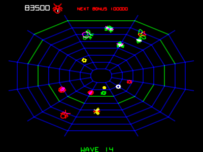
Image scaling
Old video game consoles ran at much lower resolutions than screens today are capable of displaying. The naïve way of upscaling an image is to perform nearest-neighbor interpolation on the pixels. However this method produces jagged results. There are a number of pixel art scaling algorithms designed specifically to address this problem.


Comparison of image scaling algorithms performed on a dolphin sprite from Super Mario World (4× magnification)
One of the earliest algorithms is EPX, developed to port LucasArts games to early Macintosh computers, which had about double the resolution of the original system. The algorithm replaces every pixel by a 2×2 block of the same color. Then, set the top left pixel in the 2×2 to the color of the left and upper neighbors of the pixels if their colors match and do the same for every pixel in the 2×2 block. Further magnification can be obtained by running the algorithm several times.
A refinement on EPX is the Eagle algorithm, which works similarly but also considers pixels adjacent diagonally. A number of similar algorithms exist which differ in the way they calculate the resulting pixels but are similar in principle, such as 2xSaI, Super 2xSaI and Super Eagle. All of these algorithms suffer from locality issues, as they only consider adjacent pixels.
A more sophisticated approach is used in the hqnx family of algorithms. First, the color difference is calculated between the magnified pixel and its 8 nearest neighbors. Then, that difference is compared to a predetermined threshold to determine whether the two pixels are close or distant. Hence, there are 256 possible combinations of the closeness of the neighboring pixels. Second, a lookup table with 256 entries is used, one entry for each combination. Each entry describes how to mix the colors in the resulting image to interpolate pixels of the filtered image. As the most computationally intensive part of the algorithm is generating the lookup table, the algorithm performs very well in real time. Because of that, and because it delivers the best results when compared to other fast algorithms, it is used in numerous emulators. Algorithms in the hqnx family still, however, suffer from strict locality issues and cannot resolve certain ambiguities.
As a side note, there is a curious alternative in the Kopf-Lischinski algorithm. It uses a novel way to extract resolution-independent vector images from pixel images. The vector image can then be used to magnify the image by an arbitrary amount without feature degradation. The algorithm resolves features in the input image and converts them into regions with smoothly varying shading that are separated by piecewise-smooth contour curves. Although it produces some of the best-looking results, the algorithm is quite complex and it is uncertain how it would perform in a real-time setting, as it has never been used in an emulator to date.
Sound emulation
Sound hardware typically processes digital audio and then performs digital-to-analog conversion and outputs the analog signal. Sound waves are continuous signals and to process them digitally it is necessary to convert sound waves to a discrete signal. A process called sampling takes measurements of a continuous signal at regular intervals and produces a set of digital samples.

Sampling of a simple sine wave. The black dots are samples.

A sample of rain, thunder and chirping birds

A 0.1 second excerpt of the same sample
The simplest sound processing was to store samples and use them directly to generate sound. The Nyquist sampling theorem states that it suffices that the sampling frequency is at least twice the wave’s frequency for the analog signal to be completely determined by the sampling. Because the higher end of the range of human hearing is approximately 20 kHz and for technical reasons, sound is typically sampled at 44.1 kHz, a bit above 20 kHz doubled. This means that to store a single second of 8-bit mono sound, 44100 bytes are needed, which was quite prohibitive when every single kilobyte mattered.
As with graphics, space and bandwidth concerns meant chips for generating sound on-the-fly had to be developed. One type was the programmable sound generator, which generated sound waves by synthesizing several basic waveforms and combining them. Often PSGs would have a noise generator, to generate explosion and percussion sounds. An example is the SN76489 chip used in the Sega Genesis. As PSGs needed very few bits of input data to operate, they were used in the years before memory became large and affordable enough to store sound samples. The downside of PSGs was that the sound generated was rather bland.
Frequency modulation
A very popular technique called frequency modulation was used to generate better sounding audio. The equation for a frequency-modulated wave of peak amplitude A is
F = A sin(ωc t + I f(t))
An arbitrary modulating function f(t) is multiplied by the modulation (change) index I and added to the angle (ω) of the carrier sine wave. In the case that the modulating wave is also a sine wave, the equation becomes
F = A sin(ωc t + I sin(ωc t))
XXXXX To create realistic sounding instruments, operators are used, each possessing a frequency, an envelope and the capability to modulate its input using the frequency and envelope. Operators are arranged in circuits. To simulate chords, multiple FM channels are used.
This method was so pervasive in the 80s and early 90s that the patent Stanford licensed to Yamaha for the method generated over $20 million for the university in licensing fees alone before it expired in 1994, making it the second most lucrative licensing agreement up to that point in Stanford's history.
An example of a frequency modulation synthesis chip was the Yamaha YM2612 which was used in the Sega Genesis and a number of arcade systems. It was capable of six concurrent FM channels, using four operators per channel. One of the channels could be set to play digital samples instead.


FM operator circuits in the YM2612 chip
| Circuit (a) | distortion guitar, bass |
| Circuit (b) | harp, PSG-like sound |
| Circuit (c) | bass, electric guitar, brass, piano, woods |
| Circuit (d) | strings, folk guitar, chimes |
| Circuit (e) | flute, bells, chorus, bass drum, snare drum |
| Circuit (f) | brass, organ |
| Circuit (g) | xylophone, vibraphone, snare drum, tom-tom |
| Circuit (h) | pipe organ |
Circuit recommendations for mimicking instruments, found in Sega development documentation
Documentation
As discussed before, in order to emulate a specific system, the emulator has to emulate all of the components and also the system itself, therefore information is needed on how they operate. For publicly available components such as most CPUs and popular video and sound chips, there is usually ample technical documentation available from the manufacturer. However for proprietary components (such as the lockout chip on the several Nintendo consoles, such as the SNES), peripherals and the inner workings of the system, the only primary documentation is usually confidential and not always possible to find. Therefore reverse engineering is sometimes necessary — discovering how the system works by taking it apart and analyzing its workings.
A good source of information is the source code of the many open source emulators, particularly the MAME project, whose stated goal is to be a reference to the inner workings of various arcade systems, and its sister project, MESS which does the same for console systems. Although the licenses for the projects are incompatible with commonly used open source licenses, they serve as excellent secondary documentation for systems they emulate.
Gotchas
While writing Kiwi, I encountered some interesting cases of trade-offs between speed and accuracy.
Line rendering
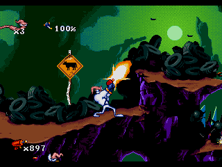
The Sega Genesis outputs graphics based on a color palette consisting of 64 9-bit colors. So under normal circumstances only 64 colors could be drawn on the screen at the same time. However in certain games a clever trick was used that changed the palette mid-frame. For example, one-third of the screen would be drawn using one set of 64 colors and then the palette would be changed and a different set of 64 colors was put in its place, thereby allowing the remaining two-thirds of the screen to be drawn using the different set of colors.
This means an emulator rendering the screen frame by frame would be inadequate, because it would miss the mid-frame palette changing effect. Below you can see a water level in Sonic the Hedgehog drawn correctly and incorrectly side by side. The game uses the trick by drawing a part of the screen that is above water with one palette and drawing the underwater part with another.
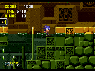 | 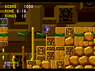 |
The naïve way to emulate a Sega Genesis frame might be to run the CPUs for 1/60 of a second and then render the frame. However, to emulate the trick properly, you need to renders each line of the screen separately and run the CPUs for 1/13340 of a second after each line (13440 is 60 times the number of lines in the screen, which in NTSC mode is 224).
Cycle accuracy
The main CPU used in the Sega Genesis, the Motorola 68000, does not execute all instructions equally fast. For example, a multiplication instruction might take 64 clock cycles to execute, while a subtraction instruction might only take 8 clock cycles. Because some games depend on these differences, it is necessary to emulate correct cycle timing of CPU instructions, instead of simply emulating their functionality. An example of this is a stage in the game Sonic the Hedgehog 2, which plays too fast when precise cycle timing is disabled.
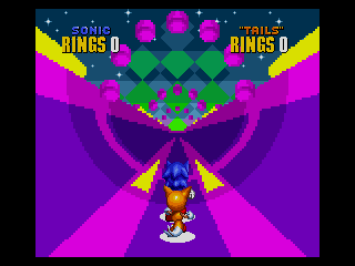
A special level in Sonic the Hedgehog 2 which requires precise instruction timing.
Video game bugs
Sometimes video game programmers make code mistakes which go unnoticed for one reason or another. One such bug persisted in a game called Bass Masters Classic Pro Edition. The Sega Genesis video processor (VDP) normally operates in what is called Mode 5. For backwards compatibility, the video chip included functionality for a mode used in earlier hardware, called Mode 4. The game Bass Masters enters the incorrect Mode 4 at one point, sets the screen resolution, and enters Mode 5 back again. The Mode 4 resolution setting is ignored in real hardware and if this is not emulated (and the resolution setting sticks), the logo screen is garbled.
 |  |
| Incorrect | Correct |
Bass Masters Classic Pro Edition
A similar thing happened when Microsoft was developing Windows 95. The game SimCity would not work in beta versions of Windows 95. Microsoft tracked down the bug and it turned out SimCity was reading memory after freeing its allocation. On modern operating systems, this results in an error, but on Windows 3.x, the operating system preceding Windows 95, this worked fine as the memory was never used again. So the Windows 95 programmers put in code that looks for SimCity and puts the memory allocator in a special mode that doesn’t free the memory right away.
References
- Neil Bradley. Ms Pacman lives! (Yahoo Groups).
- John Chowning. The Synthesis of Complex Audio Spectra by Means of Frequency Modulation. Journal of the Audio Engineering Society, 21 (7):526–534, 1973.
- Oracle Corporation. Java SE HotSpot at a Glance.
- Victor Moya del Barrio. Study of the techniques for emulation programming. Master’s thesis, FIB UPC, June 2001.
- Derek Liauw Kie Fa. 2xSaI: The advanced 2x Scale and Interpolation Engine.
- Marat Fayzullin. How to write a computer emulator.
- Shay Green. Band-Limited Sound Synthesis.
- LLVM Developer Group. The LLVM Compiler Infrastracture.
- Motorola Inc. M68000 Family Programmer’s Reference Manual. Prentice Hall, 1992.
- Johannes Kopf and Dani Lischinski. Depixelizing Pixel Art. ACM Transactions on Graphics (Proceedings of SIGGRAPH 2011), 30(4):99:1 – 99:8, 2011.
- Charles MacDonald. Sega Genesis VDP documentation, 2000.
- Anders Montonen. antime’s feeble Sega Saturn page.
- Mark Probst. Fast Machine-Adaptable Dynamic Binary Translation, 2002.
- Roger Sanders. New Documentation: An authorative reference on the YM2612.
- Joshua H. Shaffer. A Performance Evaluation of Operating System Emulators. Buchnell University, May 2004.
- David Sharp. Tarmac, Dynamically Recompiling ARM Emulator, 2001.
- Joel Spolsky. Strategy Letter II: Chicken and Egg Problems, May 2000.
- Michael Steil. Dynamic Re-compilation of Binary RISC Code for CISC Architectures. PhD thesis, Technische Universitat Munchen Institut fur Informatik, September 2004.
- Maxim Stepin. hq2x, hq3x, hq4x filters.
- Bart Trzynadlowski. Sega Genesis Emulator Save State Reference, February 2002.
- Bart Trzynadlowski. 68000 Undocumented Behavior Notes, May 2003.
- Stanford University. Music synthesis approaches sound quality of real instruments, June 1994.
Emulators
- Stéphane Dallongeville. Gens emulator.
- Dave. The DGen emulator.
- Aaron Giles. Aaron’s MAME Memories.
- Greg James, Barry Silverman, and Brian Silverman. Visual 6502 in JavaScript.
- Greg James, Barry Silverman, and Brian Silverman. Visual Transistor-level Simulation of the 6502 CPU and other chips.
- Charles MacDonald and Eke-Eke. The Genesis Plus GX emulator.
- RealityMan and Epsilon. UltraHLE.
- Nicola Salmoria and the MAME Team. MAME, Multiple Arcade Machine Emulator.
- Bernd Schmidt. UAE Amiga Emulator.
- Steve Snake. The Kega Fusion emulator.
- Michael Steil, Orlando Bassotto, and Gianluca Guida et al. Libcpu.
- Karl Stenerud. The Musashi 68000 emulator.
- Maxim Stepin and Cameron Zemek. The hqx scaling library.
- MESS team. MESS, Multi Emulator Super System.
- The VICE team. The VICE Emulator.
- VBA Team. VisualBoyAdvance emulator.